
Imagine a high-speed packaging line running at 120 bottles per minute. Suddenly, the system stops. An error message flashes on the HMI: "Sensor 7 — Signal Fault." The maintenance engineer rushes to the line, opens the control cabinet, and begins troubleshooting. Thirty minutes later, the problem is identified: the capacitive sensor selected for detecting clear plastic bottles is not reliable because the bottle's transparency and the ambient light variations are causing false triggers. This is not a sensor failure; it is a selection failure. The wrong sensor was chosen for the application, and the entire production line paid the price. This scenario plays out in factories every day, and it underscores a fundamental truth: selecting the right sensor for a PLC system is not a trivial task. It is a decision that demands a structured approach, a deep understanding of the application, and a clear grasp of the technical factors that determine sensor performance.
When selecting an IFM Industrial Sensor for PLC Systems, engineers must evaluate seven critical dimensions: sensor type and detection principle, electrical compatibility with the PLC input module, environmental conditions (temperature, moisture, dust), communication protocol integration (especially IO-Link), response time and accuracy, mounting and mechanical constraints, and long-term reliability and total cost of ownership. Each of these factors interacts with the others, and the optimal choice is rarely the most expensive sensor or the one with the longest detection range. It is the sensor that is precisely matched to the specific requirements of the application. This article will systematically guide you through each of these dimensions, providing technical insights, practical examples, and decision-making frameworks to help you select the right IFM Industrial Sensor for your PLC system.
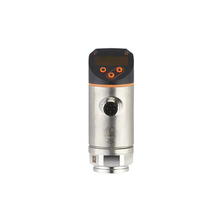
An IFM Industrial Sensor is an electronic device designed to detect physical changes in a manufacturing environment and convert those changes into electrical signals that can be interpreted by a Programmable Logic Controller (PLC). The sensor is the sensory organ of the automation system, providing the feedback necessary for the PLC to make decisions, initiate actions, and maintain control over industrial processes. Whether it is detecting the presence of a component on a conveyor, measuring the pressure in a hydraulic line, or monitoring the temperature of a motor winding, the IFM Industrial Sensor is the interface between the physical world and the digital control system.
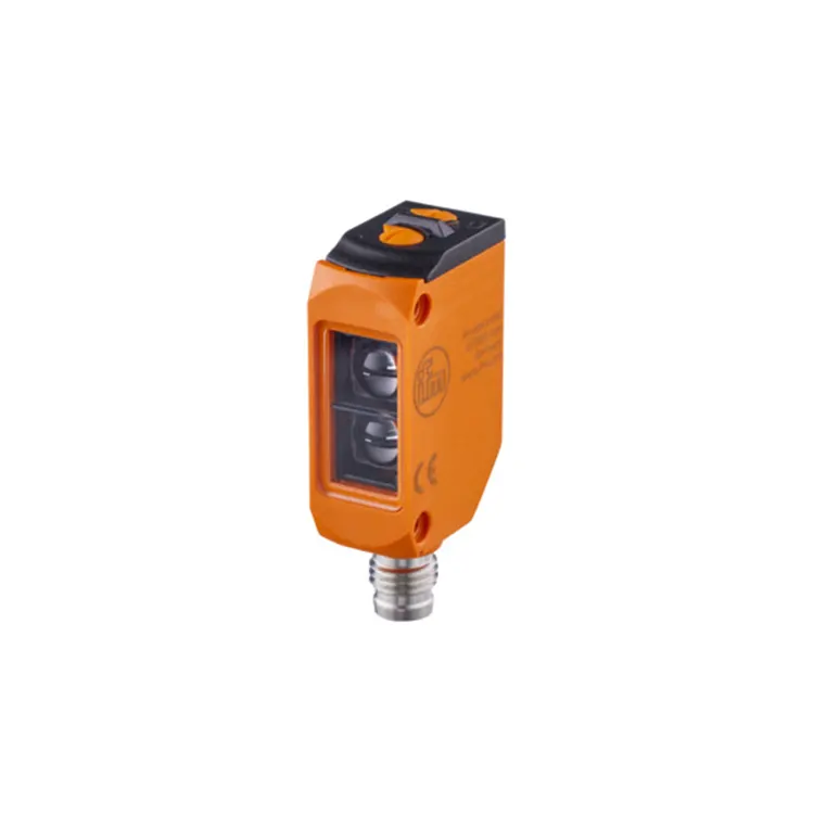
IFM is a globally recognized brand known for its wide range of industrial sensors, including inductive proximity sensors, photoelectric sensors, capacitive sensors, ultrasonic sensors, pressure sensors, temperature sensors, and flow sensors. Each sensor type is designed for a specific detection principle, making it suitable for particular applications and environments. The selection of the right IFM Industrial Sensor requires a clear understanding of the application requirements, the detection object, and the integration environment. The sensor must be compatible with the PLC in terms of electrical specifications (voltage, current, output type), communication protocol (IO-Link, PROFINET, EtherNet/IP), and mechanical mounting. The sensor's technical specifications define its performance envelope and determine whether it is capable of meeting the application's demands.
Our team at Floating Light Automation Trade Co., Ltd. specializes in helping engineers navigate this selection process. With years of experience in supplying IFM Industrial Sensor products to system integrators and manufacturers, we understand the nuances of sensor selection and can provide guidance on the most suitable sensor for your application. Whether you are designing a new system or maintaining an existing one, choosing the right IFM Industrial Sensor is critical to the success of your automation project. In the following sections, we will dive deep into the key specifications, sensor types, and integration considerations that will guide you to an optimal sensor selection.
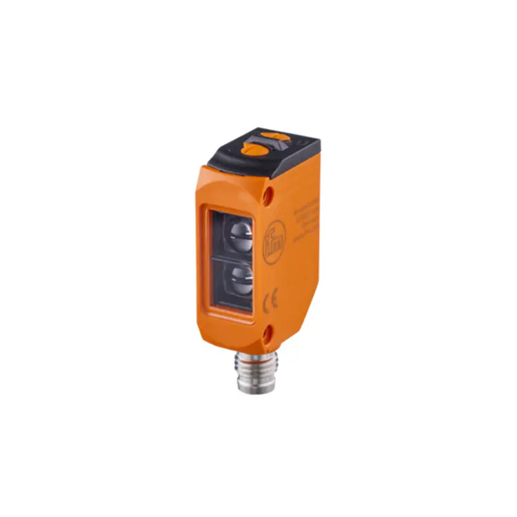
The technical specifications of an IFM Industrial Sensor provide a quantitative description of its capabilities and limitations. Understanding these specifications is essential for comparing sensor models and determining their suitability for a specific application. The following table summarizes the key technical specifications for a range of IFM Industrial Sensor types, along with their typical values and the impact on application performance.
| Specification | Inductive Proximity | Photoelectric | Capacitive | Ultrasonic | Impact on Application |
| Detection Range (mm) | 2 - 40 | 50 - 20,000 | 2 - 40 | 20 - 8000 | Determines maximum distance to target |
| Response Time (ms) | < 1 | < 1 | < 5 | < 50 | Critical for high-speed applications |
| Repeat Accuracy (%) | < 2 | < 5 | < 5 | < 2 | Ensures consistent detection over time |
| Operating Temperature (°C) | -25 to +85 | -25 to +60 | -25 to +85 | -20 to +70 | Defines usable environment range |
| Ingress Protection (IP) | IP67 | IP67 | IP67 | IP67 | Resistance to dust and water ingress |
| Output Type | PNP/NPN, IO-Link | PNP/NPN, IO-Link | PNP/NPN, IO-Link | PNP/NPN, IO-Link | Compatibility with PLC input modules |
| Housing Material | Stainless Steel | ABS/PC | Stainless Steel | Stainless Steel | Durability and chemical resistance |
When evaluating these specifications, it is essential to prioritize them based on the application requirements. For a high-speed bottling line, response time and repeat accuracy are critical. For an outdoor material handling system, the IP rating and operating temperature range are paramount. For a chemical processing application, housing material and chemical resistance are the priority. Our factory at Floating Light Automation emphasizes the importance of a balanced approach, where all specifications are considered holistically to ensure that the selected sensor meets the application's requirements and provides reliable, long-term service.
Imagine an engineer named Sarah who works at a large automotive assembly plant. She is tasked with designing a new sensing solution for a robotic welding cell. The cell must detect the presence of metal parts, verify correct orientation, and ensure that the robotic arm is in the correct position before initiating the weld cycle. Sarah has a range of sensor types available, but she must choose the right one for each function. This scenario is typical for any automation engineer, and the selection process is best approached as a systematic decision tree.
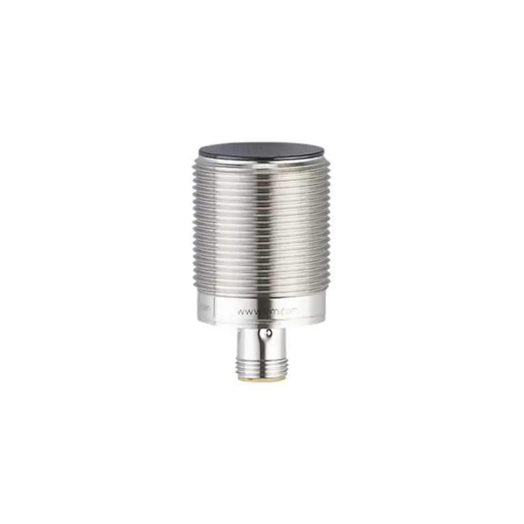
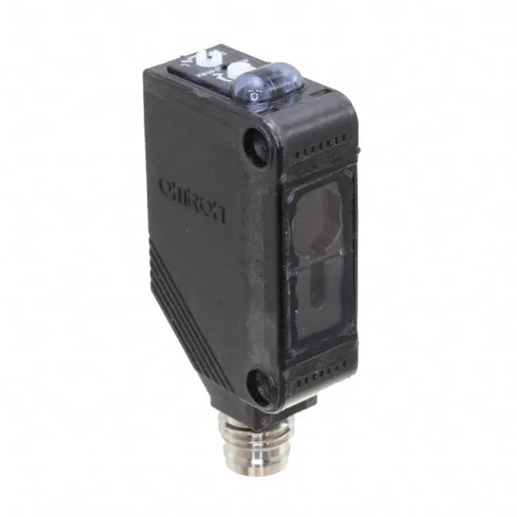
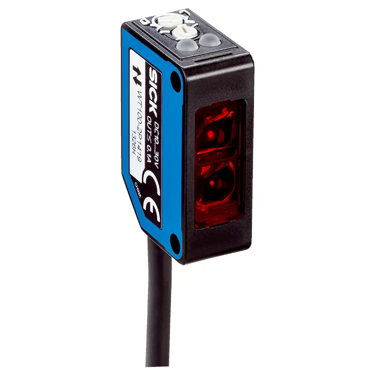
The first decision point is the detection principle. The most common types of IFM Industrial Sensor are inductive, photoelectric, capacitive, and ultrasonic. Inductive sensors are the workhorses of metal detection. They generate a high-frequency magnetic field that is altered when a metallic object enters the sensing area. They are highly reliable, fast, and unaffected by dust, dirt, or oil on the sensing face. For Sarah's welding cell, inductive sensors are the perfect choice for detecting the presence of metal parts and verifying that the robotic arm is in position. Photoelectric sensors use light to detect objects. They come in three common modes: through-beam, retro-reflective, and diffuse. Through-beam sensors have a separate emitter and receiver, providing the longest detection range and the highest reliability in dirty environments. They are ideal for detecting small parts or objects that cannot be reliably detected by other methods. In the welding cell, a retro-reflective sensor can be used to confirm that the part is in the correct orientation before welding begins.
Capacitive sensors detect changes in capacitance caused by the presence of any object, regardless of its material. They are particularly useful for detecting non-metallic objects, such as plastics, liquids, and granular materials. In a welding cell, a capacitive sensor might be used to detect the presence of a cooling fluid in a flow line or to sense the level of a lubricant. Ultrasonic sensors use sound waves to detect objects, making them ideal for applications where photoelectric sensors are unsuitable due to dust or the target's color, transparency, or reflectivity. Ultrasonic sensors are commonly used for distance measurement, level detection, and object detection in harsh environments. The table below provides a decision framework for selecting the appropriate sensor type based on the detection requirements.
| Detection Requirement | Inductive | Photoelectric | Capacitive | Ultrasonic | Recommendation |
| Detect metal object, short range | ✓ | Inductive Proximity | |||
| Detect object at long distance (1-20 m) | ✓ | Photoelectric Through-beam | |||
| Detect transparent object (glass, plastic) | ✓ | ✓ | ✓ | Photoelectric or Ultrasonic | |
| Detect non-metallic liquid or solid | ✓ | ✓ | ✓ | Capacitive or Ultrasonic | |
| Detect object in dusty environment | ✓ | ✓ | ✓ | Inductive or Ultrasonic | |
| Measure distance to object | ✓ | Ultrasonic | |||
| High-speed detection (< 1 ms) | ✓ | ✓ | Inductive or Photoelectric |
In Sarah's welding cell application, inductive sensors are the go-to choice for metal detection, while photoelectric sensors provide the flexibility for orientation verification. Capacitive and ultrasonic sensors might be considered for additional auxiliary functions. The key to successful sensor selection is to match the sensor's detection principle to the specific characteristics of the target and the environmental conditions. At Floating Light Automation Trade Co., Ltd., our team of automation specialists can help you navigate the available options and select the right IFM Industrial Sensor for your specific application.
Once the sensor type has been selected, the next critical step is to ensure electrical compatibility with the PLC system. The sensor must be correctly matched to the PLC's input module in terms of voltage, current, output type, and connection method. An electrical mismatch can result in no signal, incorrect signal, or damage to the sensor or the PLC. The most common electrical mismatches involve output type (NPN vs. PNP) and power supply voltage. Understanding these parameters is essential for a successful integration.
The output type of an IFM Industrial Sensor refers to the configuration of the transistor output that switches the signal to the PLC. There are two primary output types: NPN (sinking) and PNP (sourcing). In an NPN output, the sensor switches the signal to ground (0V) when activated, sinking current from the PLC's input. In a PNP output, the sensor switches the signal to the positive supply voltage (e.g., +24V) when activated, sourcing current to the PLC's input. The choice between NPN and PNP depends on the PLC's input module. Most European PLCs (such as Siemens) use PNP inputs, while some Asian PLCs (such as some older Omron models) use NPN inputs. It is essential to verify the PLC's input type before selecting the sensor. Many modern PLCs support both NPN and PNP, but it is always best to check the input module specifications.
In addition to output type, the sensor's supply voltage must be compatible with the PLC's power supply. Most IFM Industrial Sensors operate on DC voltages, typically 10-30V DC. Some sensors are available in AC-powered versions. The PLC system usually provides a 24V DC power supply, which is compatible with most DC sensors. However, it is essential to check the sensor's data sheet to confirm the voltage rating and ensure that the sensor is within the PLC's power supply capacity. The connection method is another compatibility factor. Sensors are available with pre-wired cables, plug-in connectors (M8, M12), or screw terminals. The choice of connection method depends on the installation environment and the need for flexibility. M12 connectors are the most common in industrial automation, providing a robust, waterproof connection that is easy to disconnect and reconnect. The following table provides an electrical compatibility checklist for selecting an IFM Industrial Sensor for a PLC system.
| Item | Check | Typical IFM Sensor Specification | Common PLC Specification |
| Supply Voltage | Compatible voltage range | 10-30V DC | 24V DC |
| Output Type | NPN or PNP compatibility | PNP or NPN (check model) | Check PLC input module specification |
| Output Signal Type | Digital or analog | Digital (PNP/NPN) or Analog (4-20mA, 0-10V) | Digital or analog input module required |
| Load Current | Max current draw | Typically 100-200 mA | Check PLC input module capacity |
| Connection Type | Compatible connector | M12, M8, or cable | Check PLC terminal block or connector |
| IO-Link Support | Communication protocol | IO-Link V1.1 | Check PLC IO-Link master capability |
By systematically checking these electrical parameters, engineers can ensure that the IFM Industrial Sensor and the PLC system are fully compatible, preventing integration headaches and ensuring reliable system operation. Our team at Floating Light Automation is well-versed in these compatibility requirements and can assist with cross-checking specifications to ensure a seamless integration.
The operating environment is a critical factor that can dramatically affect sensor performance and reliability. An IFM Industrial Sensor that works perfectly in a clean, temperature-controlled laboratory may fail quickly in a harsh industrial environment. The environment imposes constraints on the sensor's design, including its ingress protection (IP) rating, housing material, and temperature tolerance. Three typical industrial environments illustrate the range of challenges that sensors must withstand.
Case 1: Food Processing Plant — High Humidity and Chemical Washdown. A food processing plant requires sensors that can withstand frequent high-pressure washdowns with cleaning agents. The environment is wet and humid, with temperatures ranging from -10°C in cold storage to +40°C in the processing area. The sensors must be constructed with a high IP rating (IP69K for washdown) and housing material that is resistant to corrosion and chemical attack. Stainless steel housings with smooth surfaces (to prevent bacterial growth) are the preferred choice. Photoelectric sensors with robust seals are also essential to prevent moisture ingress. For this application, the IP rating and material selection are the primary selection criteria, and the sensor's detection range or speed may be secondary.
Case 2: Automotive Welding Cell — High Temperature and Electromagnetic Noise. An automotive welding cell creates a challenging environment for sensors. The area is subjected to high temperatures from welding operations, which can reach up to 150°C. Additionally, welding equipment generates significant electromagnetic interference (EMI), which can cause false triggering in sensors without adequate shielding. Sensors in this environment require high-temperature ratings (up to 85°C or higher), robust EMI shielding, and often special mounting arrangements to protect them from weld spatter. Inductive sensors with a high switching frequency and good EMI immunity are often preferred for this application. The temperature rating and EMI immunity are the critical factors.
Case 3: Cement Plant — High Dust and Vibration. A cement plant is a dusty, harsh environment with high levels of airborne particulate matter. Sensors are exposed to constant vibration from crushers and conveyors. The sensor must be dust-tight (IP6X rating) and have a housing that is robust enough to withstand continuous vibration. Photoelectric sensors are often unsuitable for this environment due to dust accumulation on the optics, which can block the light beam. Inductive sensors, with their self-contained, sealed design, are often the preferred choice. Ultrasonic sensors can also be used if they are designed with rugged housings. For this environment, the IP rating, housing material, and vibration resistance are the key selection factors.
The following table provides a summary of the environmental considerations and their impact on sensor selection.
| Environmental Factor | Typical Challenge | Sensor Specification Affected | Recommended Solution |
| Moisture / High Humidity | Water ingress, corrosion | IP Rating, Housing Material | IP67/IP69K, Stainless Steel Housing |
| Extreme Temperature | Performance degradation, failure | Operating Temperature Range | Wide-temperature sensors (-40°C to +85°C) |
| Dust / Particulate | Optical blockage, contamination | IP Rating, Sensor Type | Inductive sensors, Ultrasonic sensors, IP6X |
| Vibration / Shock | Mechanical damage, loose connections | Housing Material, Mounting | Stainless steel housing, secure mounting |
| Electromagnetic Interference (EMI) | False triggering | EMC Rating, Sensor Type | Sensors with high EMC immunity, shielded cables |
| Chemical Exposure | Housing degradation | Housing Material | PTFE or ceramic-coated housing |
Understanding the environmental demands of your application is essential for selecting an IFM Industrial Sensor that will provide reliable, long-term service. Our team at Floating Light Automation Trade Co., Ltd. can help you assess the environmental conditions of your application and recommend the appropriate sensor specifications to ensure robust performance.
In the past, industrial sensors were simple devices that delivered a binary signal to the PLC: on or off. The PLC received a signal that indicated the presence or absence of an object, and nothing more. Today, the communication landscape for industrial sensors has evolved dramatically. Modern IFM Industrial Sensor support advanced communication protocols such as IO-Link, which transforms the sensor from a simple switch into a smart, data-rich device. IO-Link is not just a communication standard; it is a paradigm shift that enhances sensor-PLC integration, unlocking new capabilities that were previously impossible.
IO-Link is a point-to-point communication protocol that enables data exchange between a sensor and the PLC (or an IO-Link master). Unlike traditional discrete I/O, where the sensor only sends a digital signal, IO-Link allows bidirectional communication. The PLC can not only read the sensor's switching status but also access detailed diagnostic information, read process parameters, and even reconfigure the sensor remotely. This is a game-changer for industrial automation. For example, an IFM Industrial Sensor with IO-Link capability can provide information on the detection quality (signal strength), the sensor's temperature, its operating hours, and even its internal diagnostic status. This data can be used by the PLC or a higher-level system for predictive maintenance, process optimization, and quality control.
The benefits of IO-Link for sensor-PLC integration are substantial. Consider a production line with hundreds of sensors. With traditional discrete I/O, the PLC only receives a limited set of signals. If a sensor fails, the PLC might detect a loss of signal, but it does not know why. The maintenance team must physically inspect the sensor to diagnose the problem. With IO-Link, the PLC receives a diagnostic alert indicating exactly which sensor is failing and why (e.g., "Sensor 37 - Signal too weak, cleaning required"). This significantly reduces troubleshooting time and minimizes downtime. Additionally, with IO-Link, the PLC can change the sensor's settings (such as the detection distance or the output timing) without requiring a physical connection to the sensor. This makes it easy to adapt the system to changing production requirements.
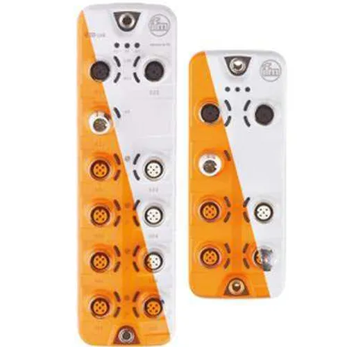
The integration of an IFM Industrial Sensor with IO-Link into a PLC system involves three components: the sensor (with IO-Link capability), the IO-Link master (a module that interfaces between the sensor and the PLC's fieldbus), and the PLC itself. The IO-Link master is connected to the PLC via a fieldbus (such as PROFINET, EtherNet/IP, or EtherCAT). The master communicates with the sensor using IO-Link protocol, and then translates the data for the PLC's fieldbus. This architecture simplifies wiring significantly: a single 4-conductor cable connects the sensor to the master, and a single fieldbus cable connects the master to the PLC. This is in stark contrast to the traditional approach, where each discrete signal requires its own dedicated wire. The following table provides a summary of the key benefits of IO-Link for sensor-PLC integration.
| Feature | Traditional Discrete I/O | IO-Link |
| Data Direction | One-way (sensor to PLC) | Bi-directional (sensor ↔ PLC) |
| Information Available | Binary signal (on/off) | Binary signal + diagnostics + process data |
| Remote Configuration | Not possible | Yes (sensor settings can be changed remotely) |
| Wiring | Individual wires for each signal | Single 4-conductor cable per sensor |
| Diagnostics | Basic (signal present/absent) | Detailed (signal quality, temperature, operating hours) |
| Predictive Maintenance | Limited | Enabled by diagnostic data |
Our team at Floating Light Automation Trade Co., Ltd. can assist with the design and implementation of IO-Link-based sensor networks, providing guidance on sensor selection, master configuration, and PLC programming. We recognize that the transition from traditional I/O to IO-Link is a strategic decision that can significantly enhance the capabilities and performance of your automation system.
When selecting an IFM Industrial Sensor, it is tempting to focus solely on the initial purchase price. However, the true cost of a sensor extends far beyond its acquisition cost. The total cost of ownership (TCO) includes the cost of installation, operation, maintenance, and, most significantly, the cost of downtime resulting from sensor failure. A sensor that is slightly more expensive but significantly more reliable can save a factory tens of thousands of dollars over its lifetime. Therefore, evaluating long-term reliability is a critical component of the selection process.
The reliability of an industrial sensor is typically quantified by its Mean Time Between Failures (MTBF). A high MTBF indicates a reliable sensor that is unlikely to fail during its expected service life. IFM sensors are known for their high quality and robust design, with MTBF values that are among the best in the industry. However, MTBF is not the only factor to consider. The sensor's robustness to environmental factors, its immunity to electromagnetic interference, and its resistance to physical stress also contribute to its long-term reliability. A sensor that is housed in a robust stainless steel housing and has a high IP rating is more likely to survive in a harsh industrial environment than one with a plastic housing and a lower IP rating.
Let's consider a scenario to illustrate the importance of TCO. A factory has 100 sensors installed on a critical production line. The factory operates 24/7, 365 days a year. Each hour of downtime costs the factory $10,000 in lost production. One sensor failure, on average, results in 2 hours of downtime for troubleshooting, replacement, and restart. If a low-cost sensor has a failure rate of 1 failure per year (MTBF of 8,760 hours), the cost of downtime from that sensor alone is $20,000 per year ($10,000 x 2 hours). If a high-quality IFM Industrial Sensor has a failure rate of 0.1 failures per year (MTBF of 87,600 hours), the cost of downtime is only $2,000 per year. The difference is $18,000 per sensor, just from downtime. This is a dramatic illustration of why TCO is more important than initial cost. The following table provides a framework for evaluating sensor reliability and TCO.
| Reliability Factor | Low Reliability Sensor | High Reliability IFM Sensor | Impact on TCO |
| MTBF (hours) | 8,760 (1 year) | 87,600 (10 years) | Lower MTBF increases downtime frequency |
| IP Rating | IP65 | IP67 / IP69K | Lower IP rating increases ingress risk |
| EMC Immunity | Basic | High | Poor EMC immunity leads to false triggers |
| Temperature Range | -10°C to +60°C | -25°C to +85°C | Narrow range limits application flexibility |
| Material Quality | Plastic housing | Stainless steel housing | Plastic degrades faster in harsh environments |
| Diagnostic Capability | None | IO-Link with diagnostics | No diagnostics increases troubleshooting time |
To evaluate the TCO of a sensor, we recommend a simple calculation: (Number of Sensors) x (Failure Rate) x (Downtime Cost per Failure) x (Expected Life). By considering the cost of downtime and the sensor's reliability, you can make an informed decision that prioritizes long-term value over short-term cost. Our team at Floating Light Automation Trade Co., Ltd. can provide the necessary data on sensor reliability and performance to support this evaluation.
Question 1: How can I confirm the compatibility of an IFM Industrial Sensor with my existing PLC system?
Answer: Compatibility depends on three key factors: output type (NPN vs. PNP), supply voltage (typically 10-30V DC), and communication protocol (standard discrete I/O or IO-Link). First, check your PLC input module specification to determine the required output type. Most European PLCs (Siemens) use PNP inputs. Then, verify that the sensor's supply voltage matches your PLC power supply (usually 24V DC). Finally, if you want to use advanced features, confirm that your PLC supports IO-Link, or that you have an IO-Link master module installed. Our team at Floating Light Automation Trade Co., Ltd. can assist with this compatibility assessment and provide a cross-reference for your specific PLC model.
Question 2: What are the key differences between NPN and PNP output sensors, and when should I choose each?
Answer: The key difference is the switching logic. In an NPN (sinking) output, the sensor connects the load to ground (0V) when activated. In a PNP (sourcing) output, the sensor connects the load to the positive supply voltage (e.g., +24V) when activated. The choice depends on your PLC's input module. Most European and modern PLCs use PNP inputs, while some older or Asian PLCs use NPN. If your PLC supports both (most do), choose the output type that is more convenient for your wiring and safety considerations. Our team can help you identify the correct output type for your PLC system.
Question 3: My sensor seems to trigger randomly. What could be causing this, and how can I fix it?
Answer: Random triggering is often caused by electromagnetic interference (EMI) from nearby motors, welding equipment, or other high-power devices. First, check the sensor's cable routing; ensure it is not running parallel to power cables. If EMI is the cause, you can use sensors with higher EMC immunity (most IFM sensors have good immunity), install shielded cables, or use a sensor with a different detection principle (e.g., inductive vs. photoelectric). Other causes include vibration, temperature fluctuations, or a misaligned sensor. We recommend a systematic inspection of the installation and environment to identify the root cause. If the problem persists, contact our automation specialists for a detailed diagnosis.
Question 4: What is the main benefit of using an IO-Link sensor over a traditional discrete sensor?
Answer: IO-Link sensors provide significant benefits over traditional discrete sensors. They offer bidirectional communication, allowing the PLC to not only read the switching state but also access detailed diagnostic and process data, including signal strength, temperature, and operating hours. This enables predictive maintenance and remote configuration, reducing downtime. IO-Link also simplifies wiring, as it uses a single 4-conductor cable for power and data. Additionally, IO-Link sensors can be configured with multiple parameter sets, allowing them to adapt to different applications without physical replacement. For a detailed assessment of the benefits for your application, contact our team at Floating Light Automation Trade Co., Ltd.
Question 5: What are the signs that an IFM Industrial Sensor is reaching the end of its service life and should be replaced?
Answer: Signs that a sensor is nearing the end of its service life include: increased response time (slower switching), reduced detection range, intermittent false triggers, visible damage to the housing or cable, and a consistent drop in signal quality (if monitored via IO-Link). If the sensor is not equipped with diagnostics, you can use a multimeter to check its output voltage or current. As a general rule, sensors in harsh environments should be replaced every 5-8 years as part of a proactive maintenance plan. Our team can provide guidance on sensor life expectancy and recommend a replacement schedule for your application.
Floating Light Automation Trade CO., LTD. is a global supplier of industrial automation components, dedicated to delivering genuine, reliable, and high-performance automation parts to system integrators, machine builders, manufacturers, and maintenance teams worldwide. We specialize in leading brands including Allen Bradley, Siemens, Omron, Keyence, SICK, and IFM, covering PLCs, HMIs, servo drives, motors, sensors, vision systems, safety components, and industrial communication modules. Every product we supply is authentic, traceable, and tested, helping our customers reduce downtime, improve productivity, and build stable automation systems.
With years of experience in industrial automation sourcing and cross-border supply, we have built a stable global supply chain and work closely with authorized channels and reliable partners. Our mission is simple: make genuine automation parts easy to find, fast to deliver, and safe to use. We serve customers across automotive, 3C electronics, food & beverage, packaging, logistics, energy, and process industries. Whether you need single spare parts, batch orders, or technical support for replacement and upgrades, our team of automation specialists is ready to provide fast quotation, professional product selection, and reliable after-sales service. At Floating Light Automation, we believe in quality, authenticity, and customer trust — we are not just a supplier, but your trusted automation partner.

Selecting the right IFM Industrial Sensor for your PLC system is a decision that requires a systematic evaluation of sensor type, electrical compatibility, environmental conditions, communication protocols, reliability, and total cost of ownership. By following the structured decision-making process outlined in this article, you can confidently select a sensor that not only meets the technical requirements of your application but also provides long-term reliability and cost-effectiveness. The key is to avoid a "one-size-fits-all" approach and to carefully match the sensor to the specific demands of the application.
At Floating Light Automation Trade Co., Ltd., we are committed to helping you navigate this complex selection process. Our team of automation specialists possesses deep technical knowledge of IFM Industrial Sensor products and their integration with PLC systems. We provide expert guidance, fast and accurate quotations, and reliable after-sales support. We invite you to contact us for any assistance with sensor selection, technical support, or product sourcing. Let us help you build a more reliable, efficient, and productive automation system. Contact Floating Light Automation Trade Co., Ltd. today for expert guidance on selecting the right IFM Industrial Sensor for your PLC system and to discover how our genuine products can enhance your industrial automation operations.